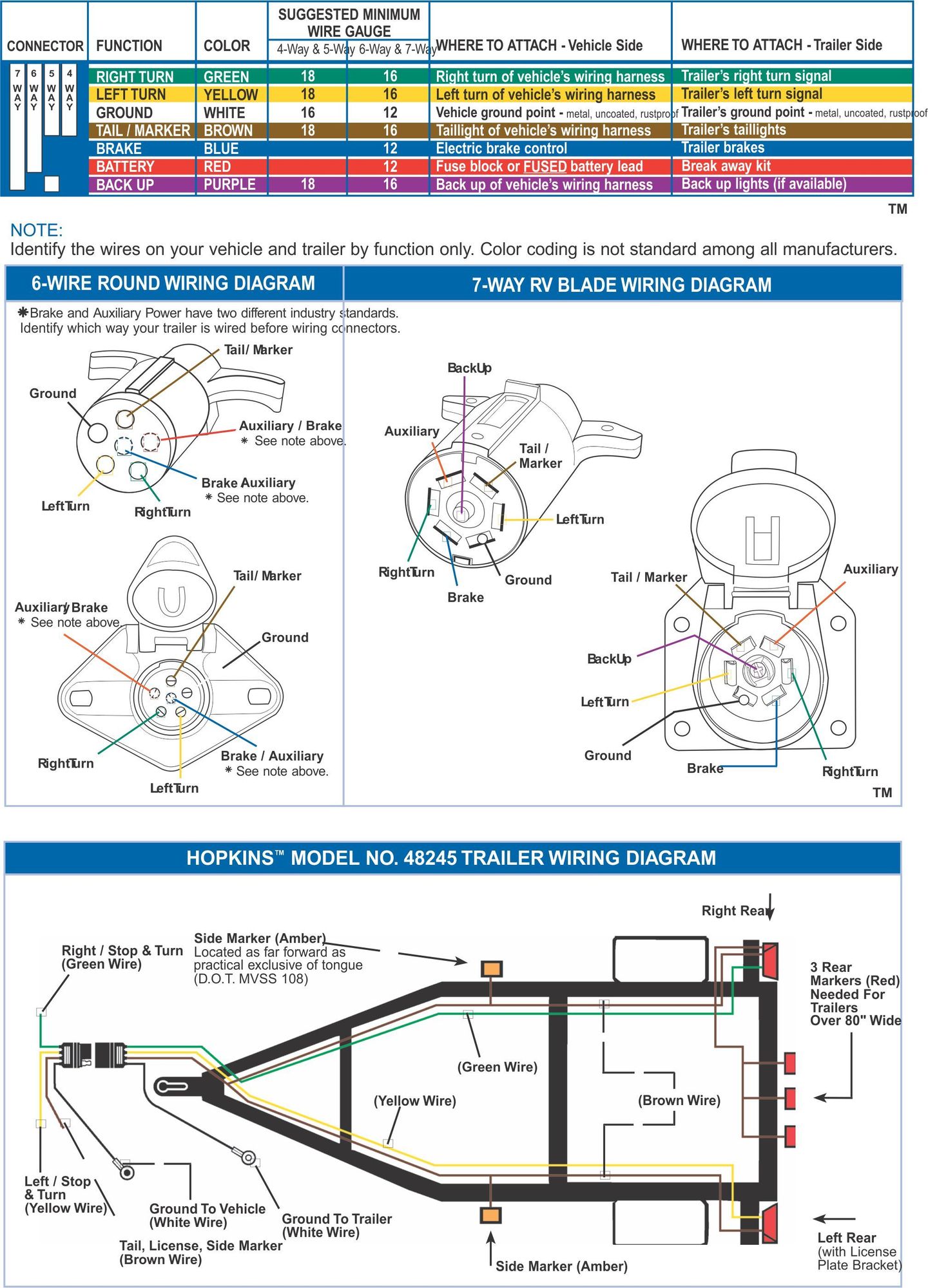
Trailer Brakes Wiring Diagram

Application Name: Standard 4 Pole Trailer Light Wiring Diagram Automotive
File Type = .Exe
Credit To @ www.pinterest.com
PDF Download
Open new tab

Application Name: Replacement Breakaway Switch for Tekonsha Trailer
File Type = .Exe
Credit To @ www.pinterest.com
PDF Download
Open new tab

Application Name: Brake Controller on my TV Airstream Forums Airstream
File Type = .Exe
Credit To @ www.pinterest.com
PDF Download
Open new tab

Application Name: Horse Trailer Wiring Diagram Trailer Wiring Connectors
File Type = .Exe
Credit To @ www.pinterest.com
PDF Download
Open new tab

Application Name: 7 pin trailer plug light wiring diagram color code (With
File Type = .Exe
Credit To @ www.pinterest.com
PDF Download
Open new tab

Application Name: Image result for 4 pin trailer wiring diagram Trailer
File Type = .Exe
Credit To @ www.pinterest.com
PDF Download
Open new tab
7 way trailer plug wiring diagram ford f250.

Trailer brakes wiring diagram. Trailer side Car side WIRING PLUG DIAGRAM. A wiring diagram is a streamlined traditional pictorial representation of an electrical circuit. It reveals the parts of the circuit as streamlined forms, as well as the power and signal connections in between the gadgets. But it also means that without wiring in a separate cable to the car battery all the power that is used to activate the trailer brakes has to be drawn from the existing trailer circuits.
Special light and wiring systems need to be installed on your tow vehicle before you can tow any trailer. This automobile is designed not only to travel one location to another but also to take heavy loads. 7 way trailer wiring diagram is explained in details in the picture and the table below: If your vehicle is not equipped with a working trailer wiring harness, there are a number of different solutions to provide the perfect fit for your specific vehicle.
They also provide a wire for a ground connection. 7 pin trailer wiring diagram with brakes. Trailer Wiring Diagrams Trailer Wiring Connectors. As the name implies, they use four wires to carry out the vital lighting functions.
A wiring diagram is a streamlined conventional pictorial depiction of an electric circuit. This automobile is designed not only to travel 1 location to another but also to carry heavy loads. Wiring Diagram for Utility Trailer with Electric Brakes Gallery Collection of wiring diagram for utility trailer with electric brakes. In the Trailer Wiring Diagram and Connector Application Chart below, use the first 5 pins,.
It really is supposed to assist all of the typical person in developing a correct program. Elecbrakes must be connected to trailer wiring circuits as outlined in the wiring diagram. A wiring diagram is a streamlined conventional pictorial representation of an electric circuit. Wiring Plug Diagram Created Date:
Pj trailers - utility trailer wiring diagram. Electric Brakes Back-up Lights Taillights Auxiliary Power Ground Electric Brakes Back-up Lights Right Turn & Brake. Various connectors are available from four to seven pins that allow for the transfer of power for the lighting as well as auxiliary functions such as an electric trailer brake controller, backup lights, or a 12V power supply for a winch or interior trailer lights. For a single axle, 14 gage is good, but for tandem axles, use 12 gage wire.
7 way plug vehicle running lights (brown) + auxilary right turn/ stop green backup lights electric brakes (blk/blue) trailer - ground (white) left turn 1 stop (yellow) 6 way plug vehicle electric brakes running lights left turn/stop xiliary right turn 1 stop Collection of ford trailer brake controller wiring diagram. The four wires control the turn signals, brake lights and taillights or running lights. 7 Pin Trailer Wiring Diagram With Brakes – Amazing 7 Wire Trailer – 7 Pin Trailer Wiring Diagram With Brakes.
Don’t skimp on wire size for your brakes. 2 Axle Trailer Brake Wiring Diagram Sample - Wiring Diagram for Tandem Axle Trailer Valid Trailer Brakes Wiring. This report will be talking Trailer Wiring Diagram Surge Brakes. Trailer Wiring and Brake Control Wiring.
If not, the arrangement will not function as it ought to be. 7-Way trailer connectors are used by the following vehicle types: Wiring Diagram for Tandem Axle Trailer Best Breakaway Kit. Large 5th wheel trailers;
These directions will likely be easy to grasp and apply. Into the flat 4-pole connector and have wire leads to provide additional functions such as powering trailer brakes, power lead for utility lights, reverse, or auxiliary power for a winch or tools.. Wiring Diagram for Tandem Axle Trailer New Wiring Diagram Trailer. Trailer Wiring Diagrams Trailer Wiring Connectors.
7 Pin Trailer Wiring Diagram With Brakes – 7 pin flat trailer wiring diagram with brakes, 7 pin rv trailer wiring diagram with brakes, 7 pin trailer wiring diagram with brakes, Every electrical arrangement is made up of various different parts. That way the trailer brakes are ready, if the tow vehicle has a 7-pin connector. On most recreational vehicles; If your trailer has 7 wires running all the way back to the brakes, then yes, you can tap into the existing wiring.
Circuits already present in trailers for powering standard loads including tail lights, blinkers and brake lights each have a capacity of 10 amps. Ensure it is sealed off and cannot create a short circuit with any other wire or the chassis. Water with the trailer wiring still connected to the vehicle. 28 Impressive How Much to Install Electric Brake Controller.
4-way trailer connectors are. The Service Brake circuit must be disconnected from an existing trailer plug.

Application Name: Trailer Wiring Diagram 7 Wire Circuit Truck to Trailer
File Type = .Exe
Credit To @ www.pinterest.com
PDF Download
Open new tab